Bifilar Coil
The structure of the Bifilar coil
A bifilar coil is an electromagnetic coil that contains two closely spaced, parallel windings. In engineering, the word bifilar describes wire which is made of two filaments or strands. It is commonly used to denote special types of winding wire for transformers. Wire can be purchased in bifilar form, usually as different colored enameled wire bonded together. For three strands, the term trifilar coil is used.
 |
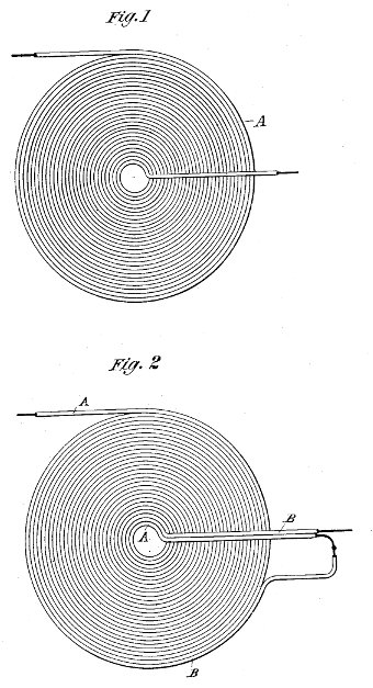
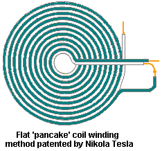
| Figure l is a diagram of a coil wound in the ordinary manner. Fig. 2 is a diagram of a winding designed |
Let A, Fig. 1, designate any given coil the spires or convolutions of which are wound upon and insulated from each other. Let it be assumed that the terminals of this coil show a potential difference of one hundred volts, and that there are one thousand convolutions; their considering any two contiguous points on adjacent convolutions let it be assumed that there will exist between them a potential difference of one-tenth of a volt. If now, as shown in Fig. 2, a conductor B be wound parallel with the conductor A and insulated from it, and the end of A be connected with the starting point of B, the aggregate length of the two conductors being such that the assumed number of convolutions or turns is the same, viz., one thousand, then the potential difference between any two adjacent points in A and B will be fifty volts, and as the capacity effect is proportionate to the square of this difference. The energy stored in the coil as a whole – will now be two hundred and fifty thousand times as great Following out this principle, I may wind any given coil either in Whole or in part, not only in the specific manner herein illustrated, but also in a great variety of ways, well known in the art, so as to secure between adjacent convolutions such potential difference as will give the proper capacity to neutralize the self-induction for any given current that may be employed. Capacity secured in this particular way possesses an additional advantage in that it is evenly distributed, a consideration of the greatest importance in many cases, and the results, both as to efficiency and economy, are the more readily and easily obtained as the size of the coils, the potential difference, or frequency of the currents are increased.
Coils composed of independent strands or conductors wound side by side and connected in series are not in themselves new, and I do not regard a more detailed description of the same as necessary. but heretofore, so far as I am aware, the objects in view have been essentially different from mine, and the results which I obtain even if an incident to such forms of winding have not been appreciated or taken advantage of.
Learn more: Tesla Bifilar Coil Magnet Generator
In carrying out my invention it is to be observed that certain facts are well understood by those skilled in the art, viz: the relations of capacity, self-induction, and the frequency and potential difference of the current. What capacity, therefore, in any given case it is desirable to obtain and what special winding will secure it, are readily determinable from the other factors which are known.
 |
| Bifilar Coil |
What I claim as my invention is –
1. A coil for electric apparatus the adjacent convolutions of which form parts of the circuit between which there exists a potential difference sufficient to secure in the coil a capacity capable of neutralizing its self-induction, as herein before described.
2. A coil composed of contiguous or adjacent insulated conductors electrically connected in series and having a potential difference of such value as to give to the coil as a whole, a capacity sufficient to neutralize its self-induction, as set forth.
NIKOLA TESLA.
Learn more: Variations of Bifilar pancake coils
The history of the Bifilar coil
German physicist Wilhelm Eduard Weber made use of the bifilar coil in his 1848 electrodynamometer. Large examples were used in inventor Daniel McFarland Cook's 1871 "Electro-Magnetic Battery" and Nikola Tesla's high frequency power experiments at the end of the 1800s. Nikola Tesla patented the Bifilar Coil on January 9, 1894, referring to it as a “Coil for Electro Magnets”.
SPECIFICATION forming part of Letters Patent No. 512,340, dated January 9, 1894. Application filed July 7.1893. Serial No. 479,804.
Application of Bifilar coils
Application of Tesla Bifilar coils and Free Energy for Generators:
1. Tesla's Radiant Energy
Tesla's intent was to condense the energy trapped between the earth and its upper atmosphere and to transform it into an electric current. He pictured the sun as an immense ball of electricity, positively charged with a potential of some 200 billion volts. The earth, on the other hand, is charged with negative electricity. The tremendous electrical force between these two bodies constituted, at least in part, what he called cosmic energy. It varied from night to day and from season to season but it is always present.
The positive particles are stopped at the ionosphere and between it and the negative charges in the ground, a distance of 60 miles, there is a large difference of voltage - something on the order of 360,000 volts. With the gases of the atmosphere acting as an insulator between these two opposite stores of electrical charges, the region between the ground and the edge of space traps a great deal of energy. Despite the large size of the planet, it is electrically like a capacitor which keeps positive and negative charges apart by using the air as a non-conducting material as an insulator.
It has been calculated that the earth's ambient state contains 1.6 x 10¹¹ joules or 4.5 megawatt-hours of electrical energy. In order to utilize this high-voltage energy you must do two things - make an energy sink and then devise a way of making the "sink" oscillate.
Such a "sink" has to be at a lower energy state than the surrounding medium and, for the energy to continually flow into it, the energy must be continually pumped out of it. Additionally, this "sink" must maintain a lower energy state while meeting the power requirements of the load attached to it. Electrical energy-watt-seconds-is a product of volts x amps x seconds. Because the period of oscillation does not change, either voltage or current has to be the variable in this system's energy equation. Bifilar wound coils are used in the system because a bifilar wound coil maximizes the voltage difference between its turns, the current is then minimized.
A coil in our system, then, will be set into oscillation at its resonant frequency by an external power source. During the "zero-point" portion of its cycle the coil will appear as one plate of a capacitor. As the voltage across the coil increases, the amount of charge it can siphon will increase. The energy that is taken into the coil through the small energy window (zero-point), call it what you will, appears to be the key to the success of this system.
It is at this zero-point where energy is condensed into positive and negative components of current. When energy escapes from the "sink" the magnetic field collapses and a strong magnetic quake is created in it's wake. A properly tuned system can capture and convert radiant energy in such a prescribed arrangement.
Application: How to Build Tesla's Radiant Energy Receiver
2. Theory of Back EMF
In electric apparatus or systems in which alternating currents are employed the self induction of the coils or conductors may, and, in fact, in many cases does operate disadvantageously by giving rise to false currents which often reduce what is known as the commercial efficiency of the apparatus composing the system or operate detrimentally in other respects. The effects of self-induction, above referred to, are known to be neutralized by proportioning to a proper degree the capacity of the circuit with relation to the self-induction and frequency of the currents. This has been accomplished here-to-fore by the use of condensers [capacitors] constructed and applied as separate instruments.
My present invention has for its object to avoid the employment of condensers [capacitors] which are expensive, cumbersome and difficult to maintain in perfect condition, and to so construct the coils themselves as to accomplish the same ultimate object.
In order to attain my object and, to properly increase the capacity of any given coil, I wind it in such way as to secure a greater difference of potential between its adjacent turns or convolutions, and since the energy stored in the coil-considering the latter as a condenser [capacitor], is proportionate to the square of the potential difference between its adjacent convolutions, it is evident that I may in this way secure by a proper disposition of these convolutions a greatly increased capacity for a given increase in potential difference between the turns.
EMF is an acronym for Electro-Motive Force.
The use of coils to reduce Back EMF will be used in ac generators and free energy transformers. Find out more about the application of Bifilar coil to remove Back EMF: Tesla Bifilar Coil Free Energy
Bifilar Coil
 Reviewed by Re-programming Life
on
9:05 PM
Rating:
 Reviewed by Re-programming Life
on
9:05 PM
Rating:


No comments: